

Introduction
Geometric primitives — boxes, cylinders, spheres, hemispheres, and pill capsules — are the building blocks of CFD domain setup. The same five shapes serve three distinct purposes depending on how they are sized relative to the geometry:
- Body of Influence (BOI): localised refinement volume for wakes, shear layers, and junctions.
- MRF zone: cylindrical or pill-shaped rotating reference frame region surrounding a fan, propeller, or rotor.
- Enclosure: large outer bounding volume establishing the fluid domain boundary.
Each primitive type maps naturally to one or more of these roles:
boi_type |
Shape | BOI | MRF zone | Enclosure |
|---|---|---|---|---|
"box" |
Rectangular cuboid | Wake boxes, junction refinement | — | Outer fluid domain |
"cylinder" |
Right circular cylinder | Axisymmetric wake refinement | Fan, propeller, rotor region | Cylindrical tunnel domain |
"hemisphere" |
Dome cap | Nose/leading-edge refinement | — | — |
"sphere" |
Full sphere | Compact omnidirectional source | — | Spherical far-field domain |
"pill" |
Cylinder + hemisphere cap | Streamlined body BOI | Elongated rotor region | — |
"frustum" |
Tapered cylinder | Tapered wake/nacelle refinement | Tapered rotor region | Tapered tunnel domain |
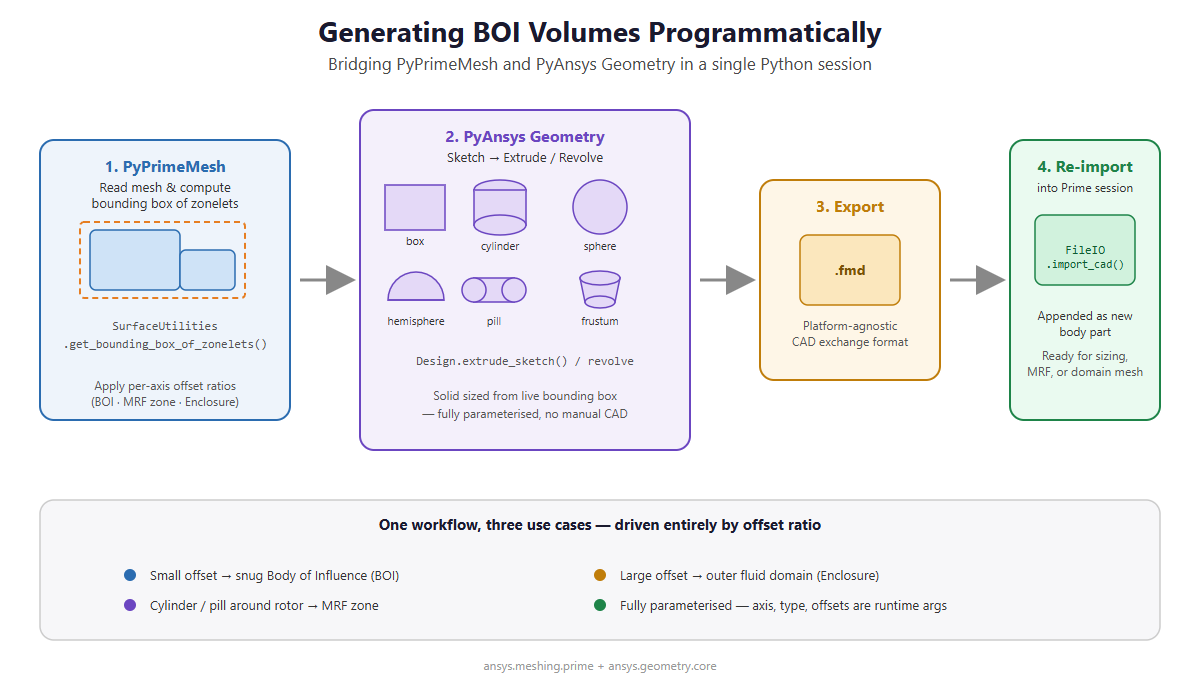
This guide shows how to eliminate that step by writing custom Python helper classes that generate all geometry programmatically, sized from the mesh's own bounding box at runtime. Key advantages over a manual CAD workflow:
- One tool, three use cases — primitive type and offset ratio determine the intent.
- Always up-to-date — bounding boxes derive from live mesh zonelets, adapting automatically when geometry changes.
- Fully parameterised — axis direction, primitive type, and offsets are all runtime parameters.
- Single script — mesh reading, CAD creation, and re-import run in one Python session.
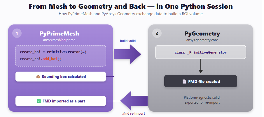
The solution bridges two PyAnsys packages:
| Package | Role |
|---|---|
PyPrimeMesh (ansys.meshing.prime) |
Reads mesh, computes bounding boxes from zonelets, imports final primitive |
PyAnsys Geometry (ansys.geometry.core) |
Constructs and exports the CAD solid as an .fmd file |
About the
.fmdformat. FMD (Fluent Meshing Data) is Ansys's platform-agnostic binary CAD exchange format. It stores the solid body in a self-contained, OS-independent representation readable on Windows, Linux, or any Ansys-supported platform — no native CAD kernel required. This makes.fmdthe ideal intermediate format when the geometry server and meshing session run on different machines or operating systems.
No CAD application is opened by the user. The entire pipeline — from reading a mesh file to appending a fully formed primitive volume — runs from a single Python script.
Code Structure
The solution is built around three Python classes you will implement:
_BBox                — plain data container for six bounding-box coordinates
_PrimitiveGenerator  — drives PyAnsys Geometry to build one primitive solid
  ├─ box             — rectangular profile extruded along an axis
  ├─ cylinder        — circular profile extruded along an axis
  ├─ hemisphere      — quarter-circle profile revolved 360° to form a dome cap
  ├─ sphere          — circumscribed sphere centred on the bounding box midpoint
  ├─ pill            — cylinder with a hemispherical cap merged at one end
  └─ frustum         — tapered circular profile extruded along an axis
PrimitiveCreator     — public API; orchestrates bounding-box extraction,
                       offsetting, CAD generation, and Prime re-import
_BBox — Bounding Box Container
class _BBox:
    def __init__(self, xmin, ymin, zmin, xmax, ymax, zmax) -> None:
        self.xmin = xmin
        self.ymin = ymin
        self.zmin = zmin
        self.xmax = xmax
        self.ymax = ymax
        self.zmax = zmax
A lightweight value object holding the six axis-aligned extents of the target region. It can be populated manually or converted from a Prime BoundingBox result.
Step 1 — Querying and Sizing the Bounding Box
The key differentiator of this workflow is deriving the bounding box directly from face zonelets rather than hard-coding coordinates. Implement a PrimitiveCreator class whose constructor queries the tight axis-aligned bounding box of any list of face zonelet IDs using prime.SurfaceUtilities.get_bounding_box_of_zonelets:
surf = prime.SurfaceUtilities(model=self.model)
computed_bounding_box = surf.get_bounding_box_of_zonelets(
    zonelets=self.face_zonelets_list
)
Once the bounding box is known, expand each face independently using per-axis offset ratios before passing it to _PrimitiveGenerator. A small ratio keeps the primitive snug for a BOI; a large ratio expands it into an enclosure:
offset_ratio = {
    "xmin_ratio": 0.0,   # no offset upstream (e.g. inlet flush with geometry)
    "ymin_ratio": 0.2,   # expand 20 % of y-length on the negative-y face
    "zmin_ratio": 0.2,
    "xmax_ratio": 0.1,   # expand 10 % of x-length on the positive-x face
    "ymax_ratio": 0.2,
    "zmax_ratio": 0.2,
}
Recompute the coordinates with the ratios applied:
self.bounding_box_coordinates = prime.BoundingBox(
    model=self.model,
    xmin=bbox.xmin - x_length * offset_ratio["xmin_ratio"],
    ymin=bbox.ymin - y_length * offset_ratio["ymin_ratio"],
    zmin=bbox.zmin - z_length * offset_ratio["zmin_ratio"],
    xmax=bbox.xmax + x_length * offset_ratio["xmax_ratio"],
    ymax=bbox.ymax + y_length * offset_ratio["ymax_ratio"],
    zmax=bbox.zmax + z_length * offset_ratio["zmax_ratio"],
)
Ratios greater than 1 produce large enclosure volumes; values near 0 produce snug BOI or MRF refinement zones. Expose a single public method add_boi that drives the full pipeline:
def add_boi(self):
    self.__create_boi()   # generates and saves the .fmd file via PyAnsys Geometry
    self.__append_boi()   # imports the .fmd back into the Prime model
Step 2 — Implementing the Primitive Geometry Functions
All five primitives are implemented inside a _PrimitiveGenerator class. Each method follows the same pattern:
- Set length units to millimetres via
DEFAULT_UNITS.LENGTH = UNITS.mm. - Derive axis lengths and cross-section radius from the bounding box.
- Build a
Sketchon aPlaneanchored at the correct origin. - Extrude or revolve the sketch into a solid body.
Shared Helpers
Before looking at individual primitives, two private helpers are used by all of them:
def __bbox_axis_lengths(self):
    distance_x = abs(self.bbox.xmax - self.bbox.xmin)
    distance_y = abs(self.bbox.ymax - self.bbox.ymin)
    distance_z = abs(self.bbox.zmax - self.bbox.zmin)
    return distance_x, distance_y, distance_z

def __cross_section_radius(self, distance_x, distance_y, distance_z):
    # Inscribed radius of the cross-section perpendicular to axis_direction
    if self.axis_direction == "x":
        return min(distance_y, distance_z) / 2
    elif self.axis_direction == "y":
        return min(distance_x, distance_z) / 2  # fixed: was min(distance_x + distance_z)
    elif self.axis_direction == "z":
        return min(distance_x, distance_y) / 2  # fixed: was min(distance_x + distance_y)
    else:
        raise ValueError(
            f"axis_direction must be 'x', 'y', or 'z', got '{self.axis_direction}'"
        )
__cross_section_radius returns the largest circle that fits within the rectangular cross-section perpendicular to the chosen axis — i.e. half the shorter dimension of that face.
1. Box
The simplest primitive. A rectangular profile is sketched on a plane perpendicular to X and extruded along X by the full bounding-box length.
def __create_box(self):
    DEFAULT_UNITS.LENGTH = UNITS.mm
    distance_x, distance_y, distance_z = self.__bbox_axis_lengths()

    sketch_plane = Plane(
        origin=Point3D([self.bbox.xmin, 0, 0]),
        direction_x=UNITVECTOR3D_Y,
        direction_y=UNITVECTOR3D_Z,
    )
    bounding_box_sketch = Sketch(sketch_plane)
    bounding_box_sketch.box(
        center=Point2D([
            self.bbox.ymin + (distance_y / 2),
            self.bbox.zmin + (distance_z / 2),
        ]),
        width=distance_y,
        height=distance_z,
    )
    self.design.extrude_sketch(
        name=self.boi_name, sketch=bounding_box_sketch, distance=distance_x
    )
Key geometry call: Sketch.box() + Design.extrude_sketch()
The sketch plane is placed at xmin with its local axes along Y and Z, so the extrusion travels in the +X direction for distance_x.
Note: Beyond the box, several other primitive geometries can be produced by the same generator simply by changing the orientation and profile passed to the sketch/extrude/revolve calls — for example a cylinder (circular profile extruded along
axis_direction), a hemisphere (quarter-circle profile revolved 360° to form a dome cap), a sphere (circumscribed about the bounding box), a pill/capsule (cylinder with a hemisphere cap merged via Boolean union), and a frustum (tapered profile extruded along an axis). These follow the same bounding-box-driven approach shown above and are omitted here for brevity.
Step 3 — Dispatching the Correct Primitive
Add a single public create_boi method to _PrimitiveGenerator that selects the geometry function by name, writes the .fmd file, and shuts down the geometry service:
def create_boi(self):
    if self.boi_type == "box":
        self.__create_box()
    elif self.boi_type == "cylinder":
        self.__create_cylinder()
    elif self.boi_type == "sphere":
        self.__create_sphere()
    elif self.boi_type == "hemisphere":
        self.__create_hemisphere()
    elif self.boi_type == "pill":
        self.__create_pill()
    elif self.boi_type == "frustum":
        self.__create_frustum()
    self.__write_cad_file()
    self.__close_geometry_services()
Once the solid is built the design is exported to an .fmd file — a platform-agnostic format readable on any Ansys-supported OS — and the geometry service is shut down.
Step 4 — Appending to the PyPrimeMesh Session
After the CAD file is written, __append_boi uses prime.FileIO to import it back as a new body part — appended to the existing model rather than replacing it. Mesh zonelets are pruned immediately so only the geometry zonelets remain, ready for size-field assignment, MRF setup, or outer-domain meshing:
def __append_boi(self):
    file_io = prime.FileIO(self.model)
    cad_import_params = prime.ImportCadParams(
        self.model,
        part_creation_type=prime.PartCreationType.BODY,
        append=True,
    )
    file_io.import_cad(
        os.path.join(self.working_dir, f"{self.boi_name}.fmd"),
        params=cad_import_params,
    )
    part = self.model.get_part_by_name(self.boi_name)
    part.delete_topo_entities(
        prime.DeleteTopoEntitiesParams(
            self.model,
            delete_geom_zonelets=False,
            delete_mesh_zonelets=True,
        )
    )
End-to-End Usage Example
The following example shows a complete workflow: launching Prime, reading a mesh, and generating three primitives — a pill-shaped BOI, a cylinder MRF zone, and a box enclosure — each derived from a different set of zonelets.
import os
from ansys.meshing import prime

# --- Assumes PrimitiveCreator, _BBox, _PrimitiveGenerator are defined as described above ---

# --- Launch Prime ---
ansys_install = os.getenv("AWP_ROOT261")
client = prime.launch_prime(
    prime_root=os.path.join(ansys_install, "meshing", "Prime")
)
model  = client.model
mesher = prime.lucid.Mesh(model)
wrk_dir = os.path.dirname(os.path.abspath(__file__))

mesher.read(os.path.join(wrk_dir, "input_mesh.msh.gz"))

part = model.get_part_by_name("origin-solid")

# --- Extract zonelets by label ---
fuselage_zonelets = part.get_face_zonelets_of_label_name_pattern(
    "fuselage", name_pattern_params=prime.NamePatternParams(model)
)
blade_zonelets = part.get_face_zonelets_of_label_name_pattern(
    "engine_blade", name_pattern_params=prime.NamePatternParams(model)
)
all_zonelets = part.get_face_zonelets()

# --- Pill primitive as BOI around fuselage (x-axis, asymmetric offsets) ---
PrimitiveCreator(
    face_zonelets_list=fuselage_zonelets,
    use_defined_bounding_box=False,
    bounding_box_coordinates={},
    axis_direction="x",
    use_offset_ratio=True,
    offset_ratio={
        "xmin_ratio": 0.0, "ymin_ratio": 0.2, "zmin_ratio": 0.2,
        "xmax_ratio": 0.1, "ymax_ratio": 0.2, "zmax_ratio": 0.2,
    },
    boi_name="boi-fuselage",
    boi_type="pill",
    model=model,
    working_dir=wrk_dir,
).add_boi()

# --- Cylinder primitive as MRF zone around rotating blade ---
PrimitiveCreator(
    face_zonelets_list=blade_zonelets,
    use_defined_bounding_box=False,
    bounding_box_coordinates={},
    axis_direction="x",
    use_offset_ratio=True,
    offset_ratio={k: 0.1 for k in
                  ("xmin_ratio","ymin_ratio","zmin_ratio",
                   "xmax_ratio","ymax_ratio","zmax_ratio")},
    boi_name="mrf-blade",
    boi_type="cylinder",
    model=model,
    working_dir=wrk_dir,
).add_boi()

# --- Box primitive as outer domain enclosure ---
PrimitiveCreator(
    face_zonelets_list=all_zonelets,
    use_defined_bounding_box=False,
    bounding_box_coordinates={},
    axis_direction="x",
    use_offset_ratio=True,
    offset_ratio={
        "xmin_ratio": 5, "ymin_ratio": 5,  "zmin_ratio": 5,
        "xmax_ratio": 5, "ymax_ratio": -0.01, "zmax_ratio": 5,
    },
    boi_name="enclosure",
    boi_type="box",
    model=model,
    working_dir=wrk_dir,
).add_boi()

mesher.write(os.path.join(wrk_dir, "mesh_with_bois.msh.gz"))
Alternatively, if you already know the exact bounding box coordinates, pass use_defined_bounding_box=True and supply a _BBox instance directly:
# --- Assumes _BBox and _PrimitiveGenerator are defined as described above ---

bbox = _BBox(xmin=-1750, ymin=-100, zmin=0, xmax=-917, ymax=0, zmax=100)
PrimitiveCreator(
    face_zonelets_list=[],
    use_defined_bounding_box=True,
    bounding_box_coordinates=bbox,
    axis_direction="x",
    use_offset_ratio=True,
    offset_ratio={
        "xmin_ratio": 5, "ymin_ratio": 5,  "zmin_ratio": 5,
        "xmax_ratio": 5, "ymax_ratio": -0.01, "zmax_ratio": 5,
    },
    boi_name="enclosure",
    boi_type="box",
    model=model,
    working_dir=wrk_dir,
).add_boi()
Summary
This guide has shown how to write custom Python helper classes that generate geometric primitive volumes directly from PyPrimeMesh face zonelets, without opening a CAD application. Five primitive types — box, cylinder, hemisphere, sphere, and pill — cover the full range of CFD domain objects: localised BOI refinement zones, MRF rotating regions, and outer domain enclosures. Bounding boxes are computed at runtime from face zonelets, ensuring every primitive is automatically sized to the current geometry. Per-axis offset ratios give fine-grained control over how tightly or loosely each primitive wraps its target region. Once generated, each solid is exported as an .fmd file and appended back into the Prime model in the same Python session, making the workflow fully reproducible and easy to integrate into automated meshing pipelines.
For more details, feel free to reach out on the Synopsys Developer Forum.