## On this page
# Documentation
Last update: 16.07.2025
This document is intended for developers who need to integrate AVxcelerate Sensors Simulator (AVX) in their simulation application. It describes how AVX works and how to use it. The API is composed of different protocol buffer contracts and gRPC services. In this document, the usage of the API is demonstrated in some code snippets written in C# programming language. Samples written in C++ and python programming languages are provided in the VSS API folder.
## Introduction
AVX embeds physics-based sensor models for camera, lidar and radar. It computes the sensor outputs from a virtual world model. The AVX step-by-step execution is driven by an external software (referred below as "Simulation System"). External components, for example perception algorithms, can interact with AVX through the data acquisition or sensor feedback control interfaces. In summary, the API contains different services which allow to:
- drive the sensors' simulation,
- adjust sensor parameters,
- being notified about new sensor data,
- request or read sensor data.
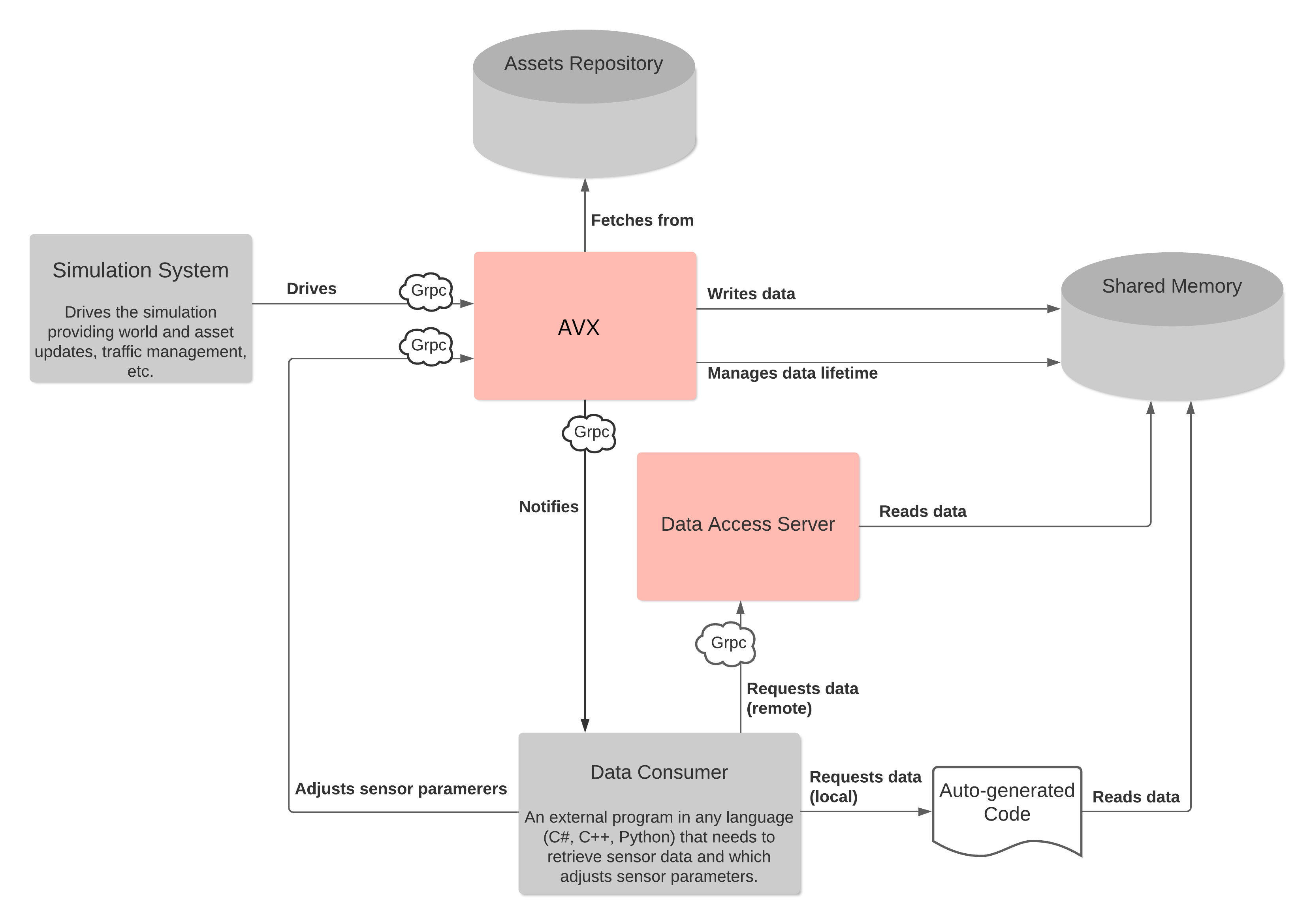
The API is designed to contain a minimum of simulation logic. This means that the responsibility for executing a blocking or a non-blocking loop is on the Simulation System side. AVX always waits until completion of each simulation command and sends back an acknowledgment when all components have been fully executed. It is the responsibility of the Simulation System to sequence the execution of all the software involved in the simulation (including AVX). In short terms - AVX is totally passive in terms of simulation scheduling.
The AVX API is composed of different [protocol buffer](https://developers.google.com/protocol-buffers) contracts and [gRPC](https://grpc.io/) services defining the interface of AVX. In gRPC, a client application can directly call a method on a server application on a different machine as if it were a local object. Another benefit of using gRPC with protocol buffers is that the contract files (.proto) can be compiled into [different programming languages](https://grpc.io/docs/#official-support).
The usage of the API is demonstrated in some samples provided in this document. These samples are written in C# programming language.
## Services
### Simulation Control
The *Simulation* service (exposed in the *simulation.proto* file) provides you with control procedures to monitor your simulation by requesting state transitions. The *ResourceUploader* service (exposed in the *upload.proto* file) allows you to upload resources as byte stream before loading them.
All possible states (started, loaded, running) and transitions (load/unload, initialize, update, stop and kill) of AVX during a simulation sequence are depicted in the following illustration.
*AVX State Machine*
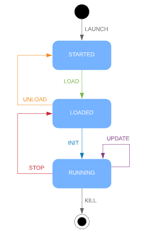
Six control procedures (corresponding to AVX 6 possible state transitions) are provided in the *Simulation* service.
> **Note:** AVX simulation sequence/logic always must be considered when using simulation control procedures to trigger state transitions. Procedures that are not consistent with the simulation transitions will end in error. Example of valid simulation sequence: LOAD > INIT > n UPDATE > STOP > UNLOAD > KILL
> **Prerequisite:** When the track and/or assets are not files but byte streams, you must use the **ResourceUploader** procedure to upload resources before being able to load them. For more information, refer to the [vss::simulation::ResourceUploader](a00738.xhtml "Upload Service.") service.
- **LOAD**: loads a new scene and configures simulation, sensors, and lighting systems. Always the **first** command.
-> AVX switches to *LOADED* state.
- **INIT**: sets the scenario to its initial state (asset positions, date and time, etc.)
-> AVX switches to *RUNNING* state and is ready to receive updates.
- **UPDATE**: applies a world update for a given simulation step and generates sensor data.
-> AVX remains in *RUNNING* state.
- **STOP**: stops the simulation
-> AVX switches to *LOADED* state.
- **UNLOAD**: allows to have a clear environment for a new simulation.
-> AVX switches to *STARTED* state.
- **KILL**: stops all AVX processes. The **KILL** command can be applied from any state. It can be used for example to end the simulation if there is a blocking problem. For a new simulation, AVX must be launched again after a **KILL** command.
> **Note:** For more information on the state transition commands, please directly refer to the [vss::simulation::Simulation](a00646.xhtml "This service provides the simulation control procedures.") service.
#### Uploading track and/or assets as stream
Instead of providing to **AVxcelerate Sensors Simulator** the path to the asset and/or track files in the **Configuration** message of the **LOAD** command, it is possible to upload those files and send their contents as a byte array using Grpc streaming capabilities. Refer to [Implementation of ResourceUploader Client](#resource_uploader_impl_ex).
### Sensors Feedback Control
The *Feedback Control* service (exposed in the *feedback\_control.proto* file) allows you to update sensor parameters during the simulation. It can only be used when AVX is in RUNNING state and has been started with the –feedbackControl [process argument](https://ansyshelp.ansys.com/account/secured?returnurl=/Views/Secured/corp/v232/en/Optis_UG_VSS/Optis/UG_VSS/R_UG_VSS_simulation_arguments.html).
The process (external software) you will develop will be running as a closed-loop simulation to update sensor parameters in real-time. It will retrieve sensor outputs, analyze them and if needed adjust them for the next output produced. The update of parameters sent to AVX will depend on your algorithms and defined thresholds.
> **Note:** Updating one or several sensor parameters through the Feedback Control triggers a sensor reload. Thus, a certain latency (more or less significant depending on your configuration) can be observed for the updated frame to be generated. Only three parameters can be updated without requiring a sensor reload: the camera gain, exposure and time encoding.
The Feedback Control is available for the following sensor parameters:
- Camera Sensor
Focal length | Wavelength of Focal length | Chromatic Dispersion presets | Focal Shift | Aperture values | Distortion values | Imager resolution | Exposure time | Readout noise values | Thermal noise values | Native bit depth | Gain | Output mode values | Time encoding
- Lidar Sensor
All lidar parameters.
For certain lidar parameters (rotating or flashing), the feedback control is only applied at the end of the frame: Rotation speed | Firing sequence | Firing frequency | Power | Responsivity | Aperture area | Pulse shape and duration | Max current | Max number of returns
- Radar Sensor
All radar parameters **except** for:
- Antenna Tx/Rx: Ids | Polarization | Horizontal and Vertical power beam width | Pattern identity (File) | Peak gain
- Mode: Id | Waveform | Center frequency | Transmission power
The Feedback Control also allows you to activate or deactivate a radar mode during the simulation.
> **Note:** To know the modes IDs of the radars included in the sensor layout, you can [read the sensor configuration](https://ansyshelp.ansys.com/account/secured?returnurl=/Views/Secured/corp/v232/en/Optis_UG_VSS/Optis/UG_VSS/T_UG_VSS_reading_a_sensor_configuration.html) or use the Sensor Labs.
> **Note:** The complete list of available feedback control parameters can also directly be found in the proto file: [vss::feedback\_control::FeedbackControl](a00178.xhtml "AVX Feedback Control Service.") service.
### Lighting System Control
The *Lighting System Control* service allows you to retrieve and update lighting system parameters during the simulation. This service can only be accessed when AVX is in RUNNING state, has been started with the –lightingSystemControl [process argument](https://ansyshelp.ansys.com/account/secured?returnurl=/Views/Secured/corp/v232/en/Optis_UG_VSS/Optis/UG_VSS/R_UG_VSS_simulation_arguments.html), and when a lighting system has been loaded during the simulation configuration.
> **Note:** For more information and a complete list of available lighting system control parameters, please refer to the [vss::lighting\_system\_control::LightingSystemControl](a00450.xhtml "Lighting System Control Service.") service.
### Sensor Data Access
The *Sensor Data Access* services allow an external software to be notified anytime a sensor data is produced and to retrieve the data. The requested sensor response can then be parsed to be processed with your own algorithm.
#### Notifications
During the simulation, sensors produce data according to their assigned frequency. An external software can subscribe to the sensor data notifications stream using the `SensorDataNotifier` service. AVX then streams notifications to the subscriber when new sensor data is produced.
Notifications are sent in a `SensorDataDescription` message which contains all the needed information to identify and acquire the data produced by a sensor during a simulation step.
Depending on the `output_splitting` value in the simulation parameters ([vss::simulation::SimulationParameters](a00650.xhtml "Contains simulation parameters per sensor id. These parameters define the accuracy of the simulation,...")), a sensor can produce multiple data during one single simulation step. All unique data identifiers along with some metadata are stored in the repeated `data_by_identifiers` field. The metadata contains information about the publisher's host address, the data access server port if available, and the characteristics of the data. The metadata also allows identification and filtering to access only data of interest.
> **Note:** The fields `data_id` and `metadata` in the message `SensorDataDescription` contain values only if the data is not split. They are deprecated and kept only to ensure backward compatibility. Please prefer using the field `data_by_identifiers` to access data identifiers and metadata.
> **Note:** For a complete description of this service, please refer to the [vss::data\_access::SensorDataNotifier](a00162.xhtml "AVX Sensor Data Notifier Service.") service.
> **Note:** If `data_by_identifiers` does not provide the data access server port, this means that the data is only available via shared memory.
#### Sensor Data Acquisition
During a simulation the data produced by the sensors are added to a data store which holds the data in the shared memory. Once a notification about a new sensor output is received, the data can be requested using the unique data identifiers which are specified in the notifications.
Three different methods can be used to acquire the sensor data produced in a simulation:
- requesting it using the RPC [vss::data\_access::DataAccess::RequestData](a00114.xhtml#a019e9686eeb9db392e20086aa8ff63f0).
- requesting it through stream using the RPC [vss::data\_access::DataAccess::RequestDataStream](a00114.xhtml#af63c79b3e02fbeea6139f232e4371191).
- accessing it directly from the shared memory.
Accessing the sensor data directly from the shared memory is more performant than accessing it from the RPC. But, accessing the data directly from the shared memory requires the external software accessing the data and AVX being executed on the same machine. Accessing the data from the RPC through stream allows the user to bypass the 2 gigabytes limit from proto.
The AVX API contains some classes which implement the data access from the shared memory for Windows and Unix-based systems and for different programming languages (C#, C++, Python). This plugin allows you to use the same service definition for the access from shared memory and the access via RPC. For more details refer to [vss::data\_access::DataAccess](a00114.xhtml "AVX Sensor Data Access Service.") and the [Implementation of Sensor Data Acquisition](#implementation_sensor_data_acquisition) section.
#### Data Lifetime
The data will be held in the data store until it is released. The frequency at which the data is released depends on the data retention strategy defined in the `DataRetentionStrategy.config.json` configuration file (delivered with AVX installation, located in the executable folder). For now, one single retention strategy is available and consists in defining the amount of data which is stored in parallel for each sensor.
##### Example
In this example, the data produced during the last two simulation steps is retained. This means that when the data for simulation step `n` is created, the data produced in step `n-2` is released from the store.
> **Warning:** A data which is released is lost.
{
"strategies": [
{
"maxStoredData": 2
}
]
}
#### Data Format
The sensor data stored in the shared memory is serialized using the [vss::sensor\_data::SensorData](a00574.xhtml "Defines the structure of the data which was produced by a single sensor for one simulation step.") proto message. Therefore, the data buffer, received from the data request, must be parsed using this proto contract.
The Camera Output (Image) and Imager Output (Injection) of physics-based camera sensors can be stored unserialized by setting the sensor parameter `serialize_data` in [vss::simulation::SimulationParameters](a00650.xhtml "Contains simulation parameters per sensor id. These parameters define the accuracy of the simulation,...") to `false`.
By default, the sensor data contains all data produced by one single sensor during one simulation step. For example, the sensor data of a lidar sensor can contain point-cloud, waveform and contribution map data, depending on the simulation parameters provided during the loading phase. However, the data produced by a radar sensor can be split per mode or per transmitter, using the `output_splitting` field in the simulation parameters. In this case, the radar data are stored in shared memory as follows:
- **MODE**: for each mode one `SensorData` message is created containing the data of this single mode.
> **Note:** When the Tx waveform report is activated and the data split per mode, one Tx waveform report will be contained in the data of each mode.
- **TRANSMITTER**: for each Tx antenna one `SensorData` message is created containing the data of this single Tx antenna
> **Note:** When the Tx waveform report is activated and the data split per Tx, the same Tx waveform report will be contained in the data of each Tx antenna of one mode.
In the data notification, the field `data_by_identifiers` contains all data identifiers together with their metadata produced by one single sensor in one single simulation step.
### Ground Truth Data Helper
The *Ground Truth Data Helper* service (exposed in the [vss::ground\_truth\_access::GroundTruthDataHelper](a00446.xhtml "AVX Ground Truth Helper Service.") file) allows you to retrieve ground truth data from a sensor during a simulation. This service can only be accessed when AVX is in LOADED or RUNNING state.
- Contribution dictionnary
If a lidar sensor is loaded in the simulation, with the *contribution* simulation parameter set to *true*, a contribution dictionary can be requested using the *GetContributionDictionary* rpc method, with a sensor identifier as parameter. The returned data is a *ContributionDictionary* ([vss::ground\_truth\_access::ContributionDictionary](a00422.xhtml "This message contains a dictionary used to relate each entity ID in the contribution output to the de...")).
- Pixel segmentation tag color map
If a camera sensor is loaded in the simulation, with the generatePixelSegmentation parameter set to true, the tag/color map used by pixel segmentation algorithm can be requested using the GetPixelSegmentationTagColorMap rpc method. The returned message is a PixelSegmentationTagColorMap containing TagColorMap data.
> **Notes** >- Same TagColorMap data can be used in SimulationParameters.PixelSegmentationMapping to freely assign tag/color associations. All tags that are not associated with a color by the user are automatically assigned with a unique color by AvxSensors. >- The tag/color map is common to all camera sensors.
## Implementation Examples
This section describes how to prepare your own component for interacting with the different AVX interfaces which were introduced above.
Before continuing reading, if you are not familiar with the basic principles of Protocol Buffers and gRPC, please read the getting started guides on:
- [Protocol Buffers](https://developers.google.com/protocol-buffers)
- [gRPC](https://www.grpc.io/)
### Preliminary Steps
1. Compile all the needed protobuf contracts. Please follow the instructions on the Protocol Buffers and gRPC websites. There are several tutorials and documentation available.
2. Include the generated code into your project.
Then, you can start implementing your own logic.
The following sections will give you guidance on how to use the different interfaces of AVX. The sample code is given in C# programming language. If you're programming in another programming language you can adapt the code snippets with the help of the gRPC documentation which includes examples for different programming languages.
### The AVX Internal gRPC Server
When AVX is launched with the argument `-p` for the port of the server, the AVX internal gRPC server listens for client requests on the specified host address and port.
> **Note:** The port value must be an integer and you must ensure that this port is not in use or blocked by any firewall.
To use the services of the gRPC server to interact with AVX, you need to implement a new gRPC client connecting to the server through a channel (HTTP/2 connection).
1. Create a channel.
Here is an example in C# programming language:
Channel _channel = new Channel(hostName, portValue, ChannelCredentials.Insecure);
try
{
_channel.ConnectAsync(DateTime.UtcNow.AddSeconds(5)).Wait();
}
catch (AggregateException e)
{
Log.Error($"gRPC Channel failed to connect properly with host {hostName} and port {portValue}. Please check your AVX Server before connecting");
throw new InvalidOperationException("gRPC connection failed", e);
}
2. Wait 5 seconds, if the channel cannot be opened during this period, an error is raised.
> **Note:** A gRPC channel should be reused when making gRPC calls. See also [Performance best practices with gRPC](https://docs.microsoft.com/en-us/aspnet/core/grpc/performance?view=aspnetcore-5.0#:~:text=Multiple%20gRPC%20clients%20can%20be,can%20make%20multiple%20simultaneous%20calls).
This channel will be used in the following client implementation examples.
### Implementation of Simulation Control Client
**Prerequisites**
- The [preliminary steps](#first_steps) are done: **simulation.proto** is compiled and included to your project.
- The gRPC channel is already [created](#create_grpc_channel).
- AVX is started with the following [process arguments](https://ansyshelp.ansys.com/account/secured?returnurl=/Views/Secured/corp/v232/en/Optis_UG_VSS/Optis/UG_VSS/R_UG_VSS_simulation_arguments.html):
- -p followed by the port of the AVX internal gRPC server
- when the client application will run on another machine, the -h | –host followed by the IP address of the machine on which AVX internal gRCP server is running.
**Steps**
1. Instantiate the `Simulation.SimulationClient` class from the gRPC channel. The class `SimulationClient` is generated from the protobuf contract which defines the service `Simulation`.
_client = new Simulation.SimulationClient(_channel);
2. Use the client to send the different commands to AVX and receive back the command status. Make sure your command order is compliant with AVX State Machine.
// Example of usage of the STOP command
Status status = _client.Stop(new Empty());
if (status.Code == [StatusCode](a00104.xhtml#aae2ce55b7c4bfb86a0f5f512d92c0c18).UnknownFailure)
{
// Handle error case
throw new Exception($"Stop command failed to execute properly. Message: {status.Message}");
}
// status.Code == StatusCode.Success -> Simulation is stopped
// ...
3. Implement your logic according to your needs. Refer to the [vss::simulation::Simulation](a00646.xhtml "This service provides the simulation control procedures.") service.
4. At the end of the simulation close the channel and dispose all objects.
5. Implement an error processing which sends a **KILL** command to stop AVX properly if something goes wrong in your code, otherwise AVX processes will not be closed properly, thus preventing the application from restarting.
> **Note:** **LOAD** must always be the first command sent to AVX, except if you use the **UPLOAD** command to upload the track and/or assets prior to the **LOAD** command.
**KILL** must be the last command sent to AVX.
### Implementation of ResourceUploader Client
Instead of providing to **AVxcelerate Sensors Simulator** the path to the asset and/or track files in the **Configuration** message of the **LOAD** command, it is possible to upload those files and send their contents as a byte array using Grpc streaming capabilities.
In this case
- before the **LOAD** command, use the **ResourceUploader** service to send an **UPLOAD** command for each required track or asset. The metadata of the **UPLOAD** message allows to define an identifier for this resource.
- in the configuration message of the **LOAD** command, use this identifier as **resourceIdentifier**.
> **Note**: A resource identifier shall be unique.
**Steps**
1. Instantiate the `ResourceUploader.ResourceUploaderClient` class from the gRPC channel. The class `ResourceUploaderClient` is generated from the protobuf contract which defines the service `ResourceUploader`.
_client = new ResourceUploader.ResourceUploaderClient(rpcChannel as RpcChannel);
2. Before sending the **LOAD** command, upload the resource.
> Note : In the example below the resource file is first open as stream, than byte arrays are extracted from this file stream to be sent using gRPC streaming. This example can apply to asset or track.
public async Task<Status> UploadResource(FilePath resourcePath, string resourceIdentifier)
{
var uploadResourceCall = _client.UploadResource();
// the first RequestStream should contain an identifier for the resource.
await uploadResourceCall.RequestStream.WriteAsync(new UploadRequest
{
UploadMetadata = new UploadMetaData
{
ResourceIdentifier = resourceIdentifier
}
});
// send the resource byte content (here we read the bytes from a file stream)
await using var readStream = File.OpenRead(resourcePath);
var buffer = new byte[1024 * 1024];
int count;
while ((count = await readStream.ReadAsync(buffer)) != 0)
{
await uploadResourceCall.RequestStream.WriteAsync(new UploadRequest
{
Data = UnsafeByteOperations.UnsafeWrap(buffer.AsMemory(0, count))
});
}
await uploadResourceCall.RequestStream.CompleteAsync();
return await uploadResourceCall;
}
3. In the `Configuration` message of the **LOAD** command, in the `vss.ResourceIdentifier` field set the identifier of the track or asset used in `UploadMetadata`.
### Implementation of Sensor Feedback Control
**Prerequisites**
- The [preliminary steps](#first_steps) are done: **feedback\_control.proto** is compiled and included to your project.
- The gRPC channel is already [created](#create_grpc_channel).
- AVX is started with the following [process arguments](https://ansyshelp.ansys.com/account/secured?returnurl=/Views/Secured/corp/232/en/Optis_UG_VSS/Optis/UG_VSS/R_UG_VSS_simulation_arguments.html):
- -p followed by the port of the AVX internal gRPC server
- when the client application will run on another machine, the -h | –host followed by the IP address of the machine on which AVX internal gRCP server is running.
- –feedbackControl
**Steps**
1. Instantiate the `FeedbackControl.FeedbackControlClient` class from the gRPC channel. The class `FeedbackControlClient` is generated from the protobuf contract which defines the service `FeedbackControl`.
_client = new FeedbackControl.FeedbackControlClient(_channel);
2. Wait for the simulation to be in *Running* state, see AVX State Machine above.
3. At any time in *Running* state, you can send a request to adjust sensor parameters by calling the `FeedbackControl.FeedbackControlClient.Send()` method with appropriate parameters and get the feedback status:
// Example for camera
FeedbackControl feedback = new FeedbackControl
{
sensorId = "vehicle\_front\_camera",
feedbackControlCameraParameters = new FeedbackControlCameraParameters
{
gain = 1.3,
injectionTime = 100
}
};
Status status = _client.Send(feedback);
if (status.Code == [StatusCode](a00104.xhtml#aae2ce55b7c4bfb86a0f5f512d92c0c18).UnknownFailure)
{
// Handle error case
throw new Exception($"Send feed back command failed. Message: {status.Message}");
}
// status.Code == StatusCode.Success -> go on with your logic
4. Implement your logic according to your needs. Refer to the [vss::feedback\_control::FeedbackControl](a00178.xhtml "AVX Feedback Control Service.") service.
> **Note:** The *sensor\_id* must be filled for each request. The id must match the sensor id as defined in the sensor configuration given to AVX. Otherwise, you will receive an error status.
> **Note:** At least one of the sensor parameter must be provided at each call. You can also provide multiple parameters for one sensor in a single request.
### Implementation of Lighting System Feedback Control
**Prerequisites**
- The [preliminary steps](#first_steps) are done: **lighting\_system\_control.proto** is compiled and included to your project.
- The gRPC channel is already [created](#create_grpc_channel).
- AVX is started with the following [process arguments](https://ansyshelp.ansys.com/account/secured?returnurl=/Views/Secured/corp/v232/en/Optis_UG_VSS/Optis/UG_VSS/R_UG_VSS_simulation_arguments.html):
- -p followed by the port of the AVX internal gRPC server
- when the client application will run on another machine, the -h | –host followed by the IP address of the machine on which AVX internal gRCP server is running.
- –lightingSystemControl
**Steps**
1. Instantiate the `LightingSystemControl.LightingSystemControlClient` class from the gRPC channel. The class `LightingSystemControlClient` is generated from the protobuf contract which defines the service `LightingSystemControl`.
_client = new LightingSystemControl.LightingSystemControlClient(_channel);
2. Wait for the simulation to be in *Running* state, see AVX State Machine above.
3. At any time in *Running* state you can send a:
- Set request to update lighting system parameters by calling the `LightingSystemControl.LightingSystemControlClient.Set()` method with appropriate parameters and get the feedback status.
- Get request to retrieve the current lighting system state by calling the `LightingSystemControl.LightingSystemControlClient.Set()` method with appropriate parameters.
4. Implement your logic according to your needs. Refer to the [vss::lighting\_system\_control::LightingSystemControl](a00450.xhtml "Lighting System Control Service.") service.
### Implementation of Subscription to Sensor Data Notifications
**Prerequisites**
- The [preliminary steps](#first_steps) are done: **sensor\_data\_output\_notification.proto** is compiled and included to your project.
- The gRPC channel is already [created](#create_grpc_channel).
**Steps**
1. Instantiate the `SensorDataNotifier.SensorDataNotifierClient` class from the gRPC channel. The class `SensorDataNotifierClient` is generated from the protobuf contract which defines the service `SensorDataNotifier`.
var client = new SensorDataNotifier.SensorDataNotifierClient(_channel);
2. Start AVX and subscribe to notifications. You can subscribe to notifications as soon as AVX is ready to receive RPC requests.
using (var call = client.Subscribe(new Empty()))
{
while (await call.ResponseStream.MoveNext(CancellationToken.None))
{
SensorDataDescription notification = call.ResponseStream.Current;
// Go on with your business logic e.g. filter notifications, request data, ...
}
}
> **Note:** As notifications might come in fast, you should consider treating them as fast as possible. For example analyzing notifications and requesting data outside of the *while* loop, inside another thread might be a good idea.
### Implementation of Sensor Data Acquisition
You can access the sensor data in two different ways depending on your use case.
#### Accessing the sensor data directly from the shared memory
> **Note:** To access the sensor data directly from the shared memory, the sensor and the component requesting the data must be located on the same machine.
**Prerequisites**
1. Compile all the needed protobuf contracts. Please follow the instructions on the Protocol Buffers and gRPC websites. There are several tutorials and documentation available.
2. Generate the plugin. To do so, three executables are provided in the `VSS_API > bin` folder.
Assuming you start from a given protobuf contract, you can generate extra tooling leveraging built-in `protoc` plugin mechanism.
> protoc.exe --shm_out=<shmOutputFolder> \
--plugin=protoc-gen-shm=<shm_xx_plugin.exe> \
--proto_path=<myProtoFolder> <MyProtoFile>
Where <shm\_xx\_plugin.exe> is the path to `shm_cpp_plugin.exe`, `shm_csharp_plugin.exe` or `shm_python_plugin.exe`.
You end up with an `xxx.shm.h`| `xxx.shm.cs` | `xxx.shm.py` file.
You can of course enrich an existing `protoc` command line (generating gRPC files) with `--shm_out` and `-plugin=protoc-gen-shm` options. Then you will end up with an extra `xxx.shm.h|cs|py` file, along with well known generated ones ie `xxx.pb`, `xxx.grpc.pb` & `xxx.grpc.pb`.
> **Note:** The function signature in generated `.shm` files shall be compatible with gRPC function signature. Thus, when you generate both `.shm` and gRPC files, it is recommended to use the same gRPC version that the Shm plugin version. You can find this version in the header of the generated `.shm` files.
3. Include the generated code into your project.
**Steps**
1. Start AVX and subscribe to notifications.
2. Once a notification about a new sensor data is received, the data can be acquired in one of two ways:
- doing a call with a client instance which has the same signature as the call from data access server.
- doing a static call which only needs the sensor data identifier you want to request from the shared memory.
Both methods use the same underlying code and are differentiated only in their function signature.
- Instance call:
// Create client
var channel = new Channel("localhost:50051", ChannelCredentials.Insecure);
var client = new DataAccess.DataAccessClient(channel);
// Request Data
Task<SensorDataBuffer> res = await client.RequestDataOptimized(sensorDataIdentifier);
SensorDataBuffer sensorDataBuffer = res.Result;
- Static call:
// Request Data
SensorDataBuffer sensorDataBuffer = DataAccess.DataAccessClient.RequestDataQuery(sensorDataIdentifier);
3. You can parse the received data buffer using the class `SensorData` generated from the **sensor\_data.proto** file:
if (sensorDataBuffer.Data.IsEmpty)
{
// An empty buffer is returned if data couldn't be retrieved (e.g. when data is already released)
}
else
{
// Deserialize data buffer
SensorData data = SensorData.Parser.ParseFrom(sensorDataBuffer.Data);
}
#### Accessing the sensor data using the RPC
**Prerequisites**
- The [preliminary steps](#first_steps) are done: **sensor\_data\_access.proto**, **sensor\_data\_buffer.proto** and **sensor\_data.proto** are compiled and included to your project.
- AVX is started with the following [process argument](https://ansyshelp.ansys.com/account/secured?returnurl=/Views/Secured/corp/v232/en/Optis_UG_VSS/Optis/UG_VSS/R_UG_VSS_simulation_arguments.html):
- -p followed by the port of the AVX internal gRPC server
- when the client application will run on another machine, the -h | –host followed by the IP address of the machine on which AVX internal gRCP server is running.
- -d
**Steps**
1. Create a gRPC channel to communicate with the **Data access server**. The client can only receive 4 MB by default, so you need to setup the channel and set receive message length to unlimited (-1 for unlimited).
// Specifying the host address and port number of the data access server
var endpoint = "localhost:50508"
// Instanciating the gRPC channel
var channel = new Channel(endpoint,
ChannelCredentials.Insecure,
new List<ChannelOption>
{
new ChannelOption(ChannelOptions.MaxReceiveMessageLength, -1)
});
2. Instantiate the `DataAccessClient` class from the gRPC channel. The class `DataAccessClient` is generated from the Protobuf contract which defines the service `DataAccess`.
// Create client
var client = new DataAccess.DataAccessClient(channel);
3. Start AVX with the sensor data access server (argument `-d|--dataAccessServer `) and subscribe to notifications as described above.
4. Once a notification about a new sensor data is received, you have two choices:
- [Request Data through a single proto message](#req_data_single)
- [Request Data through a stream](#req_data_stream)
##### Request Data through a single proto message
1. The data can be acquired through a single message by calling the **DataAccessClient.RequestData** method and using the unique data identifier acquired from the notification.
// Request Data
Task<SensorDataBuffer> sensorDataTask = client.RequestDataAsync(sensorDataIdentifier).ResponseAsync;
SensorDataBuffer sensorDataBuffer = sensorDataTask.Result;
2. You can parse the received data buffer using the class `SensorData` generated from the **sensor\_data.proto** file:
if (sensorDataBuffer.Data.IsEmpty)
{
// An empty buffer is returned if data couldn't be retrieved (e.g. when data is already released)
}
else
{
// Deserialize data buffer
SensorData data = SensorData.Parser.ParseFrom(sensorDataBuffer.Data);
}
##### Request Data through a stream
1. In stream mode, data is split and sent to clients in chunks. These data chunks can be acquired through a stream by calling the **DataAccessClient.RequestDataStream** method and using the unique data identifier obtained from the notification.
// Request Data
using var streamingCall = _client.RequestDataStream(sensorDataIdentifier);
2. You can concatenate the data chunks received through the stream into a byte array:
using var memoryStream = new MemoryStream();
while (await streamingCall.ResponseStream.MoveNext(CancellationToken.None))
{
memoryStream.Write(streamingCall.ResponseStream.Current.Data.ToByteArray());
}
return memoryStream.ToArray();
3. By default, the size of a stream data chunk is **256 kB**. You can modify the size of data chunk by editing the **VRXPERIENCE\_Sensors\_dataAccessServer.dll.config** file (delivered with AVX installation, located in the executable folder). To do so, change the value for the **sensorDataChunkSize** key (must be a positive integer).
<appSettings>
<add key="isDiagnosticOn"
value="false"/>
<add key="sensorDataChunkSize"
value="262144"/>
</appSettings>
### Implementation of Ground Truth Data Helper
**Prerequisite:** The [preliminary steps](#first_steps) are done: The gRPC channel is already created and the **ground\_truth\_data\_helper.proto** is compiled and included to your project.
1. Instantiate the `GroundTruthDataHelper.GroundTruthDataHelperClient` class from the gRPC channel. The class `GroundTruthDataHelperClient` is generated from the protobuf contract which defines the service `GroundTruthDataHelper`.
_client = new GroundTruthDataHelper.GroundTruthDataHelperClient(_channel);
2. Wait for the simulation to be in *Loaded* or *Running* state (see AVX State Machine above).
At any time in **Loaded** or **Running** state you can send a:
- GetContributionDictionary request to retrieve the current contribution dictionary of a lidar by calling the `GroundTruthDataHelper.GroundTruthDataHelperClient.GetContributionDictionary(SensorIdentifier)` method with the wanted sensor identifier.
- GetPixelSegmentationTagColorMap request to retrieve the tag/color map used in camera pixel segmentation algorithm by calling the `GroundTruthDataHelper.GroundTruthDataHelperClient.GetPixelSegmentationTagColorMap (new Empty())`.
3. Implement your logic according to your needs. Refer to the [vss::ground\_truth\_access::GroundTruthDataHelper](a00446.xhtml "AVX Ground Truth Helper Service.") service.