

Pwm
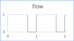
Last update: 16.07.2025The flow of Pulse-Width Modulation is 1 during the first part of the period and 0 during the second one for every period. The length of the part is defined by the duty cycle, from 0% to 100% of the period.
The figure shows the output flow for a PWM with the following inputs:
- cycles: 10
- ts (timesample): 0.1
- dutyCycle: 0.7 (70%)
- amplitude: 1
- offset: 0
Interface
| Name | Kind | Type | Comment |
|---|---|---|---|
| period | I | float | Value of the period Range: >0 |
| ts | I | float | Time sample during the period Range: >0 |
| dutyCycle | I | float | Switch reference value for on power, expressed in percent, 100% being fully on. Range: [0, 1] |
| amplitude | I | float | Gain to be applied to the output flow (default 1) |
| offset | I | float | Offset to be added to the output flow (default 0) |
| flow | O | float | Output flow |
Constraint: The ratio period / ts must be greater than 2.
Parent topic:Sources::T